Primary international aerodrome (REF AD 1.4)
This section contains additional airport specific information on runway surface condition assessment and reporting, complementing the information contained in AIP AD 1.2.
|
1
|
Ilma-alusten seisontapaikkakyltit,
rullausopasteet |
On
Ks. Visuaalisen telakoitumisen opastinjärjestelmä alla Yes See Visual docking / parking guidance system of aircraft stands below REF EFHK AD 2.5 - 1 (APDC) |
|
Use of aircraft stand ID signs, TWY guide lines
|
||
|
2
|
RWY / TWY merkinnät ja valaistus
|
RWY: ID, THR, TDZ, RCL, reunaviivat, tähtäyspistemerkinnät
TWY: keskilinjamerkinnät, reunaviivat (osittain), kiitotieodotuspaikat, väliodotuspaikat, RWY AHEAD -merkinnät ja määräävät merkinnät kiitoteille johtavilla rullausteillä (osittain) RWY: ID, THR, TDZ, RCL, side stripes, aiming point markings TWY: centre line markings, side stripes (partly), runway-holding positions, intermediate holding positions, RWY AHEAD markings and mandatory instruction markings on taxiways leading to runways (partly) RWY LGT: REF EFHK AD 2.14 TWY LGT: REF EFHK AD 2.15 |
|
RWY / TWY markings and LGT
|
||
|
3
|
Pysäytysvalorivit
|
REF EFHK AD 2.4 - 1 (ADC)
Jokaisella kiitotielle johtavalla rullaustiellä on pysäytysvalorivi. Mikäli rullaustiellä on erillinen CAT II tai CAT III kiitotieodotuspaikka, pysäytysvalorivi sijaitsee CAT II tai CAT III kiitotieodotuspaikan kohdalla. Rullausteillä ZD, ZG ja Y on lisäksi toinen pysäytysvalorivi kiitotietä lähempänä olevalla kiitotieodotuspaikalla. Each TWY leading to RWY is provided with stop bars. If TWY is provided with separate CAT II or CAT III runway-holding position, stop bars are located at the CAT II or CAT III runway-holding position. TWY ZD, ZG and Y are provided with additional stop bars located at the runway-holding position closer to the RWY. |
|
Stop bars
|
||
|
4
|
Muut kiitotien suojaustoimenpiteet
|
NIL
|
|
Other runway protection measures
|
||
|
5
|
RMK
|
Apron Spot maalausmerkinnät, REF EFHK AD 2.20
Kiitotien varoitusvalot (FLG Y), REF EFHK AD 2.4 - 1 (ADC) Apron Spot markings, REF EFHK AD 2.20 RWY guard LGT (FLG Y), REF EFHK AD 2.4 - 1 (ADC) |
REF EFHK AD 2.20, Ilma-aluksen seisontapaikat / ACFT stands
Visual Nose-in Guidance system
Instructions
Visual Nose-in Guidance system
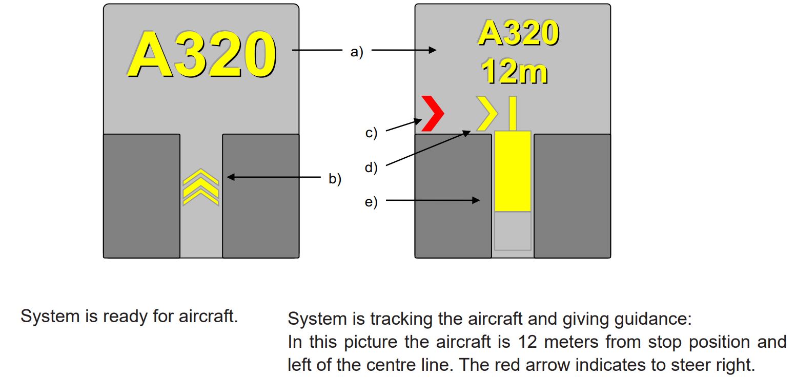
- Display indicating: Aircraft type, Distance to stop, "STOP", "OK", "TOO FAR", "WAIT", "SLOW", "ID/FAIL".
- The floating arrows indicating that the system is ready for aircraft to start docking procedure.
- Red arrow indicating the direction to turn.
- Yellow arrow shows position in relation to the centre line.
- Closing rate bar.
Instructions
- Follow taxi-in line and the centre line lights guidance.
- Check correct aircraft type is displayed.
- The floating arrows indicate that the system is ready for aircraft to start docking procedure. When the system is tracking the aircraft, the floating arrows are replaced by the closing rate bar.
- The pilot must not proceed beyond the bridge, unless the floating arrows have been superseded by the closing rate bar.
- During bad weather conditions the visibility for the docking system can be reduced. In that case the display will disable the floating arrows and display aircraft type and “SLOW”. As soon as the system detects the approaching aircraft, the closing rate bar will appear.
- “STOP/ID FAIL”: Aircraft type verification is failed. Interrupt taxiing and contact HELSINKI APRON 121.650 MHZ.
- When stop position is reached, display indicates "STOP". Correct parking is indicated as "OK".
- If aircraft overshoots the limit for correct parking, display indicates "TOO FAR".
- “WAIT”: Some object is blocking the view, aircraft is lost during tracking or system is not ready. Wait until the message is superseded by closing rate indicator and aircraft type.
- Display automatically shuts down after parking.
- In case of malfunction in the docking guidance system interrupt taxiing and contact HELSINKI APRON 121.650 MHZ.
Area 2 electronic obstacle data, as specified in ICAO Annex 15, is not available.
Electronic list containing man-made obstacles, that penetrate ICAO Annex 14 (national aviation regulation AGA M3-6) obstacle limitation surfaces and are over 3 M AGL, is available in csv format.
Csv files are available at:
These files do not comply with all the ICAO Annex 15 specifications for electronic obstacle data. The data users shall therefore carefully assess the set of available data so as to determine whether the product is adapted to their intended use.
|
1
|
Vastuussa oleva lentosääkeskus
|
LEN Etelä / LEN South
|
|
Associated MET Office
|
||
|
2
|
Palveluajat
Toissijainen lentosääkeskus |
H24
NIL |
|
Hours of service
MET Office outside hours |
||
|
3
|
TAF-ennusteet laativa lentosääkeskus
Voimassaoloaika Julkaisutiheys |
LEN Etelä / LEN South
24 HR 3 HR |
|
Office responsible for TAF preparation
Period of validity Interval of issuance |
||
|
4
|
TREND-ennusteen saatavuus
Julkaisutiheys |
H24
Päivitetään kaikkiin havaintosanomiin / Updated for all issued observation reports |
|
Availability of TREND forecast
Interval of issuance |
||
|
5
|
Säätuotteiden jakelu ja sääneuvonta
|
www.ilmailusaa.fi (self-briefing)
TEL +358 600 9 3808 Meteorologi / Forecaster - maksullinen palvelu / charged service |
|
Briefing and consultation provided
|
||
|
6
|
Sääasiakirjat
Käytettävät kielet |
Asetuksen (EU) 2017/373 edellyttämät sääkartat ja -sanomat
Charts and forms according to (EU) 2017/373 requirements EN |
|
Flight documentation
Language(s) used |
||
|
7
|
Jakelussa ja sääneuvonnassa käytettävät muut kartat ja tiedot
|
Fennoskandian alueelta saatavilla myös muuta havainto- ja ennustetietoa
Other observations and forecasts available for Fennoscandian area www.ilmailusaa.fi |
|
Charts and other information available for briefing and consultation
|
||
|
8
|
Täydentävä laitteisto lisätiedon tuottamiseksi
|
NIL
|
|
Supplementary equipment available for providing information
|
||
|
9
|
Palveltavat ATS-yksiköt
|
HELSINKI-VANTAA ATS
|
|
ATS units provided with information
|
||
|
10
|
Lisätiedot (rajoitukset yms.)
|
NIL
|
|
Additional information (limitations of service etc.)
|
|
RWY ID
|
TRUE BRG
|
DMN RWY M
|
PCN and SFC of RWY and SWY
|
THR COORD
RWY end COORD THR GUND |
THR ELEV
TDZ ELEV |
|---|---|---|---|---|---|
|
1
|
2
|
3
|
4
|
5
|
6
|
|
04L
|
047.47
|
3060 x 60
|
PCN 100/F/A/W/T
ASPH SWY: NIL |
601846.61N 0245413.93E
601953.42N 0245640.90E GUND: 59.2 FT |
THR: 133.6 FT
TDZ: 140.3 FT |
|
22R
|
227.51
|
3060 x 60
|
PCN 100/F/A/W/T
ASPH SWY: NIL |
DTHR 601952.11N 0245638.01E
601846.61N 0245413.93E GUND: 59.0 FT |
THR: 179.2 FT
TDZ: 177.5 FT |
|
04R
|
047.50
|
3500 x 60
|
PCN 102/F/B/W/T
ASPH SWY: NIL |
DTHR 601840.65N 0245610.94E
601950.49N 0245844.73E GUND: 59.0 FT |
THR: 151.6 FT
TDZ: 161.5 FT |
|
22L
|
227.54
|
3500 x 60
|
PCN 102/F/B/W/T
ASPH SWY: NIL |
601950.49N 0245844.73E
601834.10N 0245556.54E GUND: 58.8 FT |
THR: 148.6 FT
TDZ: 165.3 FT |
|
15
|
153.04
|
2901 x 60
|
PCN 108/F/B/W/T
ASPH SWY: NIL |
601948.99N 0245752.19E
601825.44N 0245917.83E GUND: 58.9 FT |
THR: 162.9 FT
TDZ: 163.4 FT |
|
33
|
333.06
|
2901 x 60
|
PCN 108/F/B/W/T
ASPH SWY: NIL |
601825.44N 0245917.83E
601948.99N 0245752.19E GUND: 58.6 FT |
THR: 147.1 FT
TDZ: 148.1 FT |
|
RWY ID
|
RWY / SWY Slope
|
SWY DMN M
|
CWY DMN M
|
STRIP DMN M
|
RESA DMN M
|
RAG
|
OFZ
|
|---|---|---|---|---|---|---|---|
|
1
|
7
|
8
|
9
|
10
|
11
|
12
|
13
|
|
04L
|
REF AOC
|
NIL
|
NIL
|
3180 x 300
|
258 x 150
|
NIL
|
Yes
|
|
22R
|
REF AOC
|
NIL
|
NIL
|
3180 x 300
|
278 x 150
|
NIL
|
Yes
|
|
04R
|
REF AOC
|
NIL
|
60 x 150
|
3620 x 300
|
140 x 150
|
NIL
|
NIL
|
|
22L
|
REF AOC
|
NIL
|
90 x 150
|
3620 x 300
|
240 x 150
|
NIL
|
Yes
|
|
15
|
REF AOC
|
NIL
|
NIL
|
3021 x 300
|
110 x 120
|
NIL
|
NIL
|
|
33
|
REF AOC
|
NIL
|
NIL
|
3021 x 300
|
90 x 120
|
NIL
|
NIL
|
|
RWY ID
RWY INT |
TORA
M |
TODA
M |
ASDA
M |
LDA
M |
RMK
|
|---|---|---|---|---|---|
|
1
|
2
|
3
|
4
|
5
|
6
|
|
04L
(WP) |
1734
|
1734
|
1734
|
NIL
|
NIL
|
|
04L
(WS) |
1942
|
1942
|
1942
|
NIL
|
NIL
|
|
04L
(WY) |
2951
|
2951
|
2951
|
NIL
|
NIL
|
|
22R
(WH) |
2945
|
2945
|
2945
|
NIL
|
NIL
|
|
22R
(WK) |
1856
|
1856
|
1856
|
NIL
|
NIL
|
|
22R
(WL) |
1856
|
1856
|
1856
|
NIL
|
NIL
|
|
22R
(WM) |
1589
|
1589
|
1589
|
NIL
|
NIL
|
|
04R
(ZG) |
1638
|
1698
|
1638
|
NIL
|
NIL
|
|
04R
(ZH) |
1708
|
1768
|
1708
|
NIL
|
NIL
|
|
04R
(ZJ) |
2009
|
2069
|
2009
|
NIL
|
NIL
|
|
04R
(ZL) |
2570
|
2630
|
2570
|
NIL
|
NIL
|
|
04R
(ZR) |
3200
|
3260
|
3200
|
NIL
|
NIL
|
|
04R
(ZS) |
3283
|
3343
|
3283
|
NIL
|
NIL
|
|
22L
(Y) |
2558
|
2648
|
2558
|
NIL
|
NIL
|
|
22L
(ZB) |
3411
|
3501
|
3411
|
NIL
|
NIL
|
|
22L
(ZD) |
2440
|
2530
|
2440
|
NIL
|
NIL
|
|
22L
(ZG) |
1886
|
1976
|
1886
|
NIL
|
NIL
|
|
15
(DEP POINT V) |
1950
|
1950
|
1950
|
NIL
|
NIL
|
|
15
(Z) |
2156
|
2156
|
2156
|
NIL
|
NIL
|
|
33
(CL) |
2524
|
2524
|
2524
|
NIL
|
NIL
|
|
33
(YF) |
1652
|
1652
|
1652
|
NIL
|
NIL
|
|
33
(YH) |
1981
|
1981
|
1981
|
NIL
|
NIL
|
|
33
(YL) |
2524
|
2524
|
2524
|
NIL
|
NIL
|
Note 1: The take-off positions, on which the reduced declared distances are based, are shown on the AOC chart concerned indicated with "REDUCED DECLARED DISTANCES CALCULATION POINT" symbols.
Note 2: The take-off positions on the runway are not marked by painted markings or sign boards with the exception of DEP POINT V which is provided with a sign board.
|
RWY ID
|
APCH LGT
type LEN INTST |
THR LGT
colour WBAR |
VASIS
(MEHT) PAPI |
TDZ LGT
LEN |
RCL LGT LEN
spacing colour INTST |
REDL
LEN spacing colour INTST |
RENL
colour WBAR |
SWY LGT
LEN colour |
RMK
|
|---|---|---|---|---|---|---|---|---|---|
|
1
|
2
|
3
|
4
|
5
|
6
|
7
|
8
|
9
|
10
|
|
04L
|
CAT II / III
900 M W LIH R LIL |
G
LIH WBAR |
PAPI
Left side/3° (55 FT) |
W
LIH 900 M |
LIH
0-2160 M, W; 2160-2760 M, R / W; 2760-3060 M, R CAT II / III Longitudinal spacing 15 M |
W
LIH YCZ 600 M |
R
LIH |
NIL
|
NIL
|
|
22R
|
CAT II / III
900 M W LIH R LIL |
G
LIH WBAR |
PAPI
Left side/3° (54 FT) |
W
LIH 900 M |
LIH
60-2160 M, W; 2160-2760 M, R / W; 2760-3060 M, R CAT II/III |
W
LIH YCZ 600 M |
R
LIH |
NIL
|
NIL
|
|
04R
|
CAT I
900 M W LIH R LIL BTN 270 - 900 M |
G
LIH WBAR |
PAPI
Left side/3° (55 FT) |
NIL
|
LIH
240-2540 M, W; 2540-3140 M, R / W; 3140-3440 M, R CAT II Longitudinal spacing 15 M |
W
LIH YCZ 600 M |
R
LIH |
NIL
|
NIL
|
|
22L
|
CAT II / III
900 M W LIH R LIL |
G
LIH |
PAPI
Left side/3° (58 FT) |
W
LIH 900 M |
LIH
0-2540 M, W; 2540-3140 M, R / W; 3140-3440 M, R CAT II Longitudinal spacing 15 M |
W
LIH YCZ 600 M |
R
LIH |
NIL
|
NIL
|
|
15
|
CAT I
900 M W LIH R LIL |
G
LIH |
PAPI
Left side/3° (56 FT) |
W
LIH 900 M |
LIH
0-2000 M, W; 2000-2600 M, R / W; 2600-2900 M, R Longitudinal spacing 15 M |
W
LIH YCZ 600 M |
R
LIH |
NIL
|
NIL
|
|
33
|
SIMPLE
420 M W LIH R LIL |
G
LIH |
PAPI
Left side/3.5° (63 FT) |
NIL
|
LIH
0-2000 M, W; 2000-2600 M, R / W; 2600-2900 M, R Longitudinal spacing 15 M |
W
LIH YCZ 600 M |
R
LIH |
NIL
|
NIL
|
|
1
|
ABN / IBN sijainti, ominaistiedot ja
toiminta-ajat |
|||||||||||||||||||||||||||||||||||||||||||||||||||||||||||||||||||||||||||||||||||||||||||||||||||||||||||||||||||||||||||||||||||||||||||||||||||||||||||||||||||||||||||||||||||||||||||||||||||||||||||||||||||||||||||||||||||||||||||||||||||||||||||||||||||||||||||||||||||||||
|
ABN / IBN location, characteristics and hours of operation
|
||||||||||||||||||||||||||||||||||||||||||||||||||||||||||||||||||||||||||||||||||||||||||||||||||||||||||||||||||||||||||||||||||||||||||||||||||||||||||||||||||||||||||||||||||||||||||||||||||||||||||||||||||||||||||||||||||||||||||||||||||||||||||||||||||||||||||||||||||||||||
|
2
|
LDI sijainti ja valaistus
WDI sijainti ja valaistus |
LDI: NIL
WDI: COORD: 601927N 0245807E, LGTD COORD: 601944N 0245631E, LGTD COORD: 601850N 0245434E, LGTD COORD: 601845N 0245928E, LGTD COORD: 601842N 0245927E, LGTD COORD: 601845N 0245912E, LGTD |
||||||||||||||||||||||||||||||||||||||||||||||||||||||||||||||||||||||||||||||||||||||||||||||||||||||||||||||||||||||||||||||||||||||||||||||||||||||||||||||||||||||||||||||||||||||||||||||||||||||||||||||||||||||||||||||||||||||||||||||||||||||||||||||||||||||||||||||||||||||
|
LDI location and LGT
WDI location and LGT |
||||||||||||||||||||||||||||||||||||||||||||||||||||||||||||||||||||||||||||||||||||||||||||||||||||||||||||||||||||||||||||||||||||||||||||||||||||||||||||||||||||||||||||||||||||||||||||||||||||||||||||||||||||||||||||||||||||||||||||||||||||||||||||||||||||||||||||||||||||||||
|
3
|
TWY reuna- ja keskilinjavalot
|
|
||||||||||||||||||||||||||||||||||||||||||||||||||||||||||||||||||||||||||||||||||||||||||||||||||||||||||||||||||||||||||||||||||||||||||||||||||||||||||||||||||||||||||||||||||||||||||||||||||||||||||||||||||||||||||||||||||||||||||||||||||||||||||||||||||||||||||||||||||||||
|
TWY edge and centre line lighting
|
||||||||||||||||||||||||||||||||||||||||||||||||||||||||||||||||||||||||||||||||||||||||||||||||||||||||||||||||||||||||||||||||||||||||||||||||||||||||||||||||||||||||||||||||||||||||||||||||||||||||||||||||||||||||||||||||||||||||||||||||||||||||||||||||||||||||||||||||||||||||
|
4
|
Varavoima-asema
Vaihtoaika |
AVBL
1 SEC |
||||||||||||||||||||||||||||||||||||||||||||||||||||||||||||||||||||||||||||||||||||||||||||||||||||||||||||||||||||||||||||||||||||||||||||||||||||||||||||||||||||||||||||||||||||||||||||||||||||||||||||||||||||||||||||||||||||||||||||||||||||||||||||||||||||||||||||||||||||||
|
Secondary power supply / switch-over time
|
||||||||||||||||||||||||||||||||||||||||||||||||||||||||||||||||||||||||||||||||||||||||||||||||||||||||||||||||||||||||||||||||||||||||||||||||||||||||||||||||||||||||||||||||||||||||||||||||||||||||||||||||||||||||||||||||||||||||||||||||||||||||||||||||||||||||||||||||||||||||
|
5
|
RMK
|
NIL
|
|
FATO ID
|
FATO THR COORD
|
FATO ELEV FT
|
FATO DMN M
SFC MTOM Markings |
True BRG of FATO
|
Declared distance AVBL
|
APP and FATO LGT
|
RMK
|
|---|---|---|---|---|---|---|---|
|
1
|
2
|
3
|
4
|
5
|
6
|
7
|
8
|
|
H16
|
601851.30N
0245907.44E |
146.6 FT
|
310x20 M, ASPH, AUW 11000 KG,
White markings |
153.05
|
NIL
|
WHITE
LIL |
VFR only
|
|
H34
|
601842.37N
0245916.59E |
142.6 FT
|
310x20 M, ASPH, AUW 11000 KG,
White markings |
333.06
|
NIL
|
WHITE
LIL |
VFR only
|
|
Designation and lateral limits
|
Vertical limits
|
Airspace classification
|
ATS unit call sign Language(s)
|
Transition altitude
|
Hours of
applicability |
RMK
|
|---|---|---|---|---|---|---|
|
1
|
2
|
3
|
4
|
5
|
6
|
7
|
|
EFHK CTR NORTH
Area bounded by lines joining points 602443N 0244227E - 602728N 0245518E - 602651N 0250453E - 602209N 0251220E - 601629N 0251242E - 601656N 0250219E - 601552N 0250148E - 601433N 0245938E - 601302N 0245851E - 601222N 0245537E - 601302N 0244849E - 601624N 0244112E - 601936N 0243850E to point of origin. |
D
|
HELSINKI TOWER
EN |
5000 FT MSL
|
H24
|
TMZ H24
|
|
|
EFHK CTR SOUTH
Area bounded by lines joining points 601656N 0250219E - 601629N 0251242E - 601537N 0251240E - 601041N 0250300E - 601108N 0250045E - 601302N 0245851E - 601433N 0245938E - 601552N 0250148E to point of origin. |
D
|
HELSINKI TOWER
EN |
5000 FT MSL
|
H24
|
TMZ H24
|
|
SER
|
Call Sign
|
FREQ
|
HR UTC
|
SATVOICE
|
Logon address
|
RMK
|
|---|---|---|---|---|---|---|
|
1
|
2
|
3
|
4
|
5
|
6
|
7
|
|
APP
|
HELSINKI ARRIVAL
|
119.900 MHZ
|
H24
|
NIL
|
NIL
|
NIL
|
|
124.325 MHZ
|
||||||
|
119.700 MHZ
|
||||||
|
121.500 MHZ
|
||||||
|
APP
|
HELSINKI RADAR
|
119.100 MHZ
|
H24
|
NIL
|
NIL
|
NIL
|
|
129.850 MHZ
|
||||||
|
119.700 MHZ
|
||||||
|
121.500 MHZ
|
||||||
|
TWR
|
HELSINKI TOWER
|
118.600 MHZ
|
H24
|
NIL
|
NIL
|
NIL
|
|
118.850 MHZ
|
||||||
|
119.700 MHZ
|
||||||
|
121.500 MHZ
|
||||||
|
GND
|
HELSINGIN RULLAUS
HELSINKI GROUND |
121.800 MHZ
|
H24
|
NIL
|
NIL
|
Ks. EFHK AD 2.22.3, Reittiselvitys lähtevälle IFR- liikenteelle
See EFHK AD 2.22.3, En route clearance for departing IFR traffic |
|
118.125 MHZ
|
||||||
|
ATIS
|
ATIS ARR
|
135.075 MHZ
|
H24
|
NIL
|
NIL
|
EN
D-ATIS REF AIP, GEN 3.4, kohta 3.3.4. ATIS-lähetystä koskevia rajoituksia: 1. Tilanteessa, jossa ei ole kriittisiä lumivalleja ja kiitotien kunnostetun keskikaistan leveys on vähintään 45 M, ei ATIS-lähetyksessä lueta reunakaistojen tietoja. 2. Toisistaan riippuvaisten rinnakkaisten lähestymisten ollessa käytössä ilmoitetaan kiitotiekohtaisten tuulitietojen sijasta RWY 15 kosketuskohdan (METAR-mittauspiste) tuulitieto. EN D-ATIS REF AIP, GEN 3.4, para 3.3.4. Limitations in ATIS: 1. In circumstances when no critical snowbanks exist and the middle part of cleared runway area is at least 45 M, the information concerning the edges will not be reported separately. 2. During dependent parallel approaches the surface wind of TDZ RWY 15 (METAR measuring point) will be reported instead of RWY orientated surface wind. |
|
ATIS
|
ATIS DEP
|
114.200 MHZ
|
H24
|
NIL
|
NIL
|
Helsinki VOR, EN
D-ATIS REF AIP, GEN 3.4, kohta 3.3.4. ATIS-lähetystä koskevia rajoituksia: 1. Tilanteessa, jossa ei ole kriittisiä lumivalleja ja kiitotien kunnostetun keskikaistan leveys on vähintään 45 M, ei ATIS-lähetyksessä lueta reunakaistojen tietoja. 2. Toisistaan riippuvaisten rinnakkaisten lähestymisten ollessa käytössä ilmoitetaan kiitotiekohtaisten tuulitietojen sijasta RWY 15 kosketuskohdan (METAR-mittauspiste) tuulitieto. Helsinki VOR, EN D-ATIS REF AIP, GEN 3.4, para 3.3.4. Limitations in ATIS: 1. In circumstances when no critical snowbanks exist and the middle part of cleared runway area is at least 45 M, the information concerning the edges will not be reported separately. 2. During dependent parallel approaches the surface wind of TDZ RWY 15 (METAR measuring point) will be reported instead of RWY orientated surface wind. |
|
APRON
|
HELSINGIN ASEMATASO
HELSINKI APRON |
121.650 MHZ
|
H24
|
NIL
|
NIL
|
Ilma-alusten pysäköintipalvelut ja Marshalling-palvelu sekä liikelentoterminaalin palvelu
Apron management services, Marshalling service and business flight terminal services |
|
DE-ICING
|
ETÄJÄÄNPOISTOKOORDINAATTORI
REMOTE DE-ICING COORDINATOR |
133.850 MHZ
|
HO
|
NIL
|
NIL
|
Etäjäänpoistoalueen toiminnasta vastuussa oleva koordinaattori
Remote De-icing Coordinator |
|
DE-ICING
|
HELSINGIN JÄÄNPOISTOKOORDINAATTORI
HELSINKI DE-ICING COORDINATOR |
127.025 MHZ
|
HO
|
NIL
|
NIL
|
Jäänpoistotilaukset, Ks. EFHK AD 2.20.7.1.2
De-icing orders, See EFHK AD 2.20.7.1.2 |
Note: Outside the operational hours of ATS the ATIS broadcast is not monitored and may therefore be invalid.
|
Type of aid
MAG VAR CAT of ILS / MLS DECL |
ID
|
FREQ
CH |
HR UTC
|
PSN
|
DME
ELEV FT |
Service
volume radius |
RMK
|
|---|---|---|---|---|---|---|---|
|
1
|
2
|
3
|
4
|
5
|
6
|
7
|
8
|
|
DME
|
ANT
|
113.700 MHZ
(CH84X) |
H24
|
605146.83N
0250736.55E |
314 FT
|
NIL
|
NIL
|
|
DVOR/DME
(09° E 2020) (DECL 9°E) |
HEL
|
114.200 MHZ
(CH89X) |
H24
|
602016.14N
0245713.43E |
239 FT
|
NIL
|
NIL
|
|
LOC 04R
ILS CAT I (09° E 2020) |
HG
|
111.500 MHZ
|
HO
|
601954.83N
0245854.30E |
NIL
|
NIL
|
NIL
|
|
GP 04R
ILS CAT I |
HG
|
332.900 MHZ
|
H24
|
601850.02N
0245619.98E |
NIL
|
NIL
|
Angle: 3.0°
|
|
DME 04R
ILS CAT I |
HG
|
111.500 MHZ
(CH52X) |
H24
|
601850.02N
0245619.98E |
206 FT
|
NIL
|
NIL
|
|
LOC 22L
ILS CAT II (09° E 2020) |
HK
|
110.300 MHZ
|
HO
|
601827.64N
0245542.32E |
NIL
|
18 NM
|
NIL
|
|
GP 22L
ILS CAT II |
HK
|
335.000 MHZ
|
H24
|
601946.98N
0245825.22E |
NIL
|
NIL
|
Angle: 3.0°
|
|
DME 22L
ILS CAT II |
HK
|
110.300 MHZ
(CH40X) |
H24
|
601946.98N
0245825.22E |
205 FT
|
18 NM
|
NIL
|
|
LOC 15
ILS CAT I (09° E 2020) |
HL
|
109.100 MHZ
|
H24
|
601820.34N
0245923.05E |
NIL
|
NIL
|
NIL
|
|
GP 15
ILS CAT I |
HL
|
331.400 MHZ
|
H24
|
601942.01N
0245808.12E |
NIL
|
NIL
|
Angle: 3.0°
|
|
DME 15
ILS CAT I |
HL
|
109.100 MHZ
(CH28X) |
H24
|
601942.01N
0245808.12E |
220 FT
|
NIL
|
NIL
|
|
LOC 04L
ILS CAT III (09° E 2020) |
HTV
|
111.900 MHZ
|
HO
|
602001.65N
0245659.02E |
NIL
|
NIL
|
NIL
|
|
GP 04L
ILS CAT III |
HTV
|
331.100 MHZ
|
H24
|
601855.87N
0245422.73E |
NIL
|
NIL
|
Angle: 3.0°
|
|
DME 04L
ILS CAT III |
HTV
|
111.900 MHZ
(CH56X) |
H24
|
601855.87N
0245422.73E |
165 FT
|
NIL
|
NIL
|
|
LOC 22R
ILS CAT III (09° E 2020) |
HUO
|
110.700 MHZ
|
HO
|
601839.19N
0245357.62E |
NIL
|
NIL
|
NIL
|
|
GP 22R
ILS CAT III |
HUO
|
330.200 MHZ
|
H24
|
601947.87N
0245616.87E |
NIL
|
NIL
|
Angle: 3.0°
|
|
DME 22R
ILS CAT III |
HUO
|
110.700 MHZ
(CH44X) |
H24
|
601947.87N
0245616.87E |
207 FT
|
NIL
|
NIL
|
|
DME
|
KAD
|
117.500 MHZ
(CH122X) |
H24
|
600849.21N
0250451.86E |
138 FT
|
NIL
|
NIL
|
|
DME
|
ORM
|
117.300 MHZ
(CH120X) |
H24
|
605000.60N
0254543.53E |
273 FT
|
NIL
|
NIL
|
|
DME
|
PVO
|
112.800 MHZ
(CH75X) |
H24
|
601739.76N
0253518.52E |
121 FT
|
NIL
|
NIL
|
|
DME
|
VTI
|
117.000 MHZ
(CH117X) |
H24
|
602733.30N
0241438.65E |
203 FT
|
NIL
|
NIL
|
Note: Outside the operational hours of ATS the signals of radio navigation and landing aids are not monitored and may therefore be invalid.
According to the Regulation (EC) No 793/2004 of the European Parliament and of the Council Helsinki-Vantaa airport is a coordinated airport.
At a coordinated airport, access for an air carrier or any other aircraft operator is possible only if a slot has been allocated, see paras 2.20.1.1 and 2.20.1.2. below. State flights, emergency landings and humanitarian flights and flights not using airport runways for departures or landings are exempt from slot allocation.
Slot requests shall be submitted in advance to the slot coordinator, any time within the limits of the scheduling period, by SITA, by e-mail or using Online Coordination, see
www.airportcoordination.com. The request shall be submitted using the format given in the IATA Standard Schedule Information Manual (SSIM), chapter 6.
Alterations or cancellations of previously coordinated flights shall be reported without delay.
Contact information:
Slot Coordinator
Helsinki-Vantaa Slot Coordination Association ry
P.O. Box 77
FI-01531 VANTAA
SITA: HELACXH
E-mail: scr@airportcoordination.com
(slot requests only)
Address of visitors: Lentäjäntie 1 E
Additional information: www.airportcoordination.com/
Slot Coordinator
Helsinki-Vantaa Slot Coordination Association ry
P.O. Box 77
FI-01531 VANTAA
SITA: HELACXH
E-mail: scr@airportcoordination.com
(slot requests only)
Address of visitors: Lentäjäntie 1 E
Additional information: www.airportcoordination.com/
The operator or a handling agent authorized by the operator must request an airport slot for an arrival and departure as a minimum 3 hours before the planned arrival or departure time.
Further information regarding monitoring of the complience of the airport slot:
www.airportcoordination.com.
Slot requests shall be submitted by e-mail:
GAslot.efhk@finavia.fi.
Further information:+358 20 708 2720 or
www.airportcoordination.com.
www.airportcoordination.com.
Slot request shall comprise the following information:
Business Flight Terminal will confirm the slot time by e-mail to the sender. This confirmation includes, together with the information above, a slot identification (Slot-ID) which shall be included in flight plan section 18.
The aerodrome is PPR (Prior Permission Required) for aircraft which are not based at Helsinki-Vantaa.
Ground handling must be pre-appointed for all visiting business and general aviation aircraft. Prior permission should be requested through a handling agent. Permissions will not be granted by ATC (see EFHK AD 2.4).
Aircraft using EFHK as an alternate or diversion airport do not require prior permission.
Further information:
BFC@finavia.fi
See para EFHK AD 2.22.3.3
Aircraft parked at the apron shall use ground power always when available at the stand.
The use of APU shall be restricted only to unavoidable situations.
CDM procedures are mandatory for all IFR flights arriving or departing from Helsinki-Vantaa airport, except certain guarding, emergency and rescue flights etc or flight in emergency situation or other exceptional situation.
TOBT is the estimated time when aircraft is ready for immediate engines start up and/or push back after receiving clearance from TWR. An exception exists in de-icing procedures when the TOBT owned by the airline operator excludes time consumed for de-icing operations at the aircraft’s original parking position (see EFHK AD 2.20 para 7). In this case TOBT is the time when an aircraft is ready to start the de-icing process.
If the aircraft is not ready within +/-5 minutes of the last informed TOBT the TOBT must be updated accordingly. TOBT can be updated as described below. Observe, that the target start up time (TSAT) is generated based on the TOBT. Operators are encouraged to adjust TOBT as close to real as possible.
The ownership of the TOBT is at the airline or aircraft operator. Often the most practical way, however, is to agree about the update of the TOBT with your ground handling agent (see EFHK AD 2.20 para 1.3) who usually have a direct access to the CDM application. If the airline/aircraft operator or ground handling agent has no CDM rights for a particular flight the update request can be addressed directly to the CDM Management Center by phone.
The number of manual updates of the TOBT during the last TOBT-40 minutes is restricted to three (3). In case more updates are required, contact CDM Management Center in order to release the account for further updates.
CDM TOBT procedure does not replace the pilots responsibility to keep the adequate flight plan valid and within the given limits.
Time in which the flight crew can request ATC for engines start-up (and push-back).
TSAT is provided by the ATC in order to optimize departure sequence with regard to EOBT, TOBT, ATFM restrictions (CTOT), de-icing and local conditions.
First TSAT will be issued after submission of the first TOBT, but not earlier than 40 MIN prior EOBT. ATC informs pilots of the TSAT in connection of the en-route clearance.
In interval TSAT +/-5 minutes the flight crew shall request start-up and in case of NOSE-IN stand, push-back. Engines start-up or push-back shall be commenced immediately after receiving the clearance.
If the crew does not request start-up clearance within the interval TSAT +/-5 minutes and TOBT is not updated the flight is excluded from the sequence until a new TOBT is submitted.
In general, TSAT is not changed during the last TSAT-20 minutes period. However, improvement to the TSAT can be accepted by confirming (or updating) TOBT during this time manually directly to the CDM application. Also other constraints, like change in CTOT, may cause an update to the TSAT.
Changed TSAT times can be obtained via ATC (R/T), Cockpit laptop (CDM application), Docking guidance system (where available) or your ground handling agent.
Due to operational reasons ATC may provide start-up clearance regardless of the existing TSAT.
After receiving the TSAT the pilot doesn't need to update flight plan (FPL) and TOBT accordingly. However, TOBT and FPL EOBT always have to encounter with each other (TOBT has to fit to the flight plan window).
A permanent and fully automatic data exchange with the NM unit has been established. This data transfer enables highly accurate early predictions of landing and departure times. Furthermore, it allows for more accurate and efficient CTOT calculations due to the use of more accurate local target takeoff times.
The existing NM procedures continue to apply and they take the local target take-off times into consideration wherever possible.
De-icing event is part of the CDM process. For more detailed information, see para 2.20.7.
Apron Control Management / CDM Management Center
TEL: +358 20 708 3308
cdm@finavia.fi
TEL: +358 20 708 3308
cdm@finavia.fi
HELSINKI GROUND 121.800 MHZ or 118.125 MHZ
Follow-me will be provided for all A380 aircraft movements.
5.3.1. Taxiing on the apron is always subject to instructions.
Note: The ATC issues clearances for taxiing only within the ATC Service Boundary presented on the aerodrome chart. For taxiing on the apron ATC does not issue clearances but taxi instructions. See also section AD 1.1, para 7.2 and EFHK AD 2.20.7.2 (Special Procedures for Remote De-icing Apron).
5.3.2. When taxiing on the apron the aircraft shall follow the yellow taxiing guide lines. No deviations or short cuts are permitted except under the guidance of a follow-me car or after special instructions given by the appropriate ATC unit.
5.3.3. Apron Spot co-ordination points
5.3.3.1. Purpose
Apron Spots will be used as co-ordination points for both inbound and outbound traffic to/from aprons.
Note 1: Apron Spots will not be used if the markings are temporarily covered by ice or snow.
Note 2: Apron Spots shall not be used as parking stands.
5.3.3.2. Characteristics
Colour: Orange
Dimensions: A circle, diameter 7 M
Identification: Indicated by two digits
Note: Painted day markings only.
Dimensions: A circle, diameter 7 M
Identification: Indicated by two digits
Note: Painted day markings only.
5.3.3.3. Outbound traffic from aprons
5.3.3.4. Inbound traffic to apron
After receiving taxi instruction to an Apron Spot
5.3.3.5. Radiotelephony phraseology
Pilots are to use the minimum power necessary when manoeuvring on the taxiway system. This is of particular importance when manoeuvring on the apron, where jet blast can affect adjacent stands.
Stop bars are normally used in all visibility conditions.
Certain taxiway access points to the runways are fitted with both CAT I and CAT II/III holding points but only CAT II/III holding points are equipped with stop bars. Regardless of prevailing visibility conditions, an illuminated stop bar shall not be crossed unless unable to switch off for a technical reason and specifically cleared by ATC.
When LVP procedures are in force, ATC will issue a specific taxi clearance to a CAT II/III holding point.
Aircraft using RWY 04R/22L or 15/33 or FATO16/34 for landing shall contact HELSINKI GROUND 121.800 MHZ immediately after vacating the runway/FATO for taxi clearance. Aircraft vacating RWY 04L/22R or helicopters landing on Helipad Y shall remain on the appropriate TWR frequency unless otherwise instructed by ATC.
If no other instruction than aircraft stand is given the aircraft shall use the taxiway parallel to the runway to the taxiway closest to the assigned aircraft stand.
Aircraft landed at runway 22L shall not vacate runway via taxiway ZG unless otherwise instructed by ATC.
Route clearance by radio shall be requested from the appropriate ATC unit but not earlier than 25 MIN before the estimated start-up. For additional information, see EFHK AD 2.22.3.2.
Contact Helsinki Ground for start-up and push back clearance. The stand of the aircraft shall be stated in the initial contact with the ATC unit.
Taxi instructions and clearance given by ATC shall be followed when taxiing. Unless otherwise instructed the aircraft shall use the shortest possible way to the taxiway parallel to the runway to continue further to the clearance limit given by the ATC.
When delayed by CTOT, aircraft may be ordered to push and hold due to stand capacity. Instructions will be given by ATC.
5.6.1. Aircraft operators intending to use Helsinki- Vantaa airport should ensure that Mode-S transponders (if installed) are able to operate when the aircraft is on the ground.
5.6.2. Flight crew of a Mode-S-equipped aircraft shall:
Activation of the Mode S transponder means selecting AUTO mode, ON, XPNDR, or the equivalent, according to the specific installation. Selection of the STAND-BY mode will NOT activate the Mode S transponder.
5.6.3. Flight crew of aircraft equipped with Mode S having an aircraft identification feature should also set the aircraft identification. This setting is the aircraft identification specified in item 7 of the ICAO ATC Flight Plan. The aircraft identification should be entered from the request for pushback or taxi, whichever is earlier, through the FMS or the Transponder Control Panel.
6.1.1. FATO H16/H34 is within ATC service boundary. When performing take-offs from H16 or landings on H34, pilots must exercise caution and visually confirm the absence of obstacles in the front sector.
Outside the ATC service boundary at APN 4 and between taxiways CL and CN there may be ground traffic unknown to ATC. REF AIP, EFHK AD 2.5 - 1 (APDC).
7.1.1. Aircraft de-icing may only be carried out in areas specifically designated by the airport. De-icing may also be performed on Remote De-icing Apron (Aprons 6 and 8).
7.1.2. De-icing shall be requested BTN 0330-2230 UTC (0230-2130 UTC) through the Helsinki De-icing Coordinator by radio (“Helsinki De-icing Coordinator”, FREQ 127.025 MHZ). The de-icing coordinator will then inform the pilot of which de-icing stand or area to use and will forward the request to the de-icing company. Other times de-icing shall be requested via the de-icing company. Pilots are recommended to monitor the de-icing coordinator's frequency.
De-icing shall be requested 20 MIN prior to TOBT. Requests for manual treatment shall be included.
7.1.3. All queries regarding de-icing requests shall initially be made direct to the de-icing coordinator (“Helsinki De-icing Coordinator”, FREQ 127.025 MHZ).
7.1.4. Pilots must always request route clearance from Air Traffic Control before de-icing begins (when the aircraft is ready to begin de-icing). This requirement also applies when de-icing is to be carried out in aircraft parking areas.
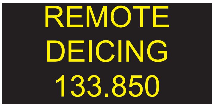
7.2.1. When de-icing is performed on the Remote Deicing Apron, ATC will hand over the aircraft at the perimeter of the apron to the Remote De-icing Coordinator (normally "Remote De-icing Coordinator" FREQ 133.850 MHZ).
7.2.2. When notifying the coordinator, pilots shall use their aircraft call sign for identification. The coordinator will direct the aircraft to one of the de-icing stands.
7.2.3. The Remote De-icing Aprons, including their entry and exit taxi lines, lie outside the normal manoeuvring area (REF EFHK AD 2.4 - 3). Pilots are reminded to proceed
with extreme caution within these areas so as not to endanger other personnel or vehicles operating in the areas. Pilots must avoid using excessive power when taxiing within these aprons.
with extreme caution within these areas so as not to endanger other personnel or vehicles operating in the areas. Pilots must avoid using excessive power when taxiing within these aprons.
7.2.4. De-icing is complete when the pilot has received final notification (in accordance with the SAE anti-icing code) by radio. On the remote de-icing apron, the final notification is considered as including the "all clear" signal. The anti-icing code cannot be given unless all the conditions of the "all clear" signal have been met. Pilots must remain on the coordinator's frequency until the anti-icing code has been received and the pilot has received instructions to contact Air Traffic Control again.
7.2.5. In the initial call to Air Traffic Control the pilot shall notify them of the flights radio call sign and the de-icing stand number being used. The aircraft must not move until taxiing instructions have been received from Air Traffic Control and acknowledged.
The aircraft visual guidance system is in use on APN 6 and APN 8.
Visual guidance system is an informative source of deicing process displayed to pilots. All communication between deicing truck and pilots occurs via VHF radio.
Visual guidance system information:
Remote deicing APN 6 and APN 8 queuing boards inform the pilot the remote de-icing frequency.
Visual guidance system at standby mode displays deicing bay number.
When taxiing to the deicing bay the pilot will be instructed to contact after the parking brakes are set.

Commencing deicing.

Hold position at deicing bay until the traffic lights have been turned on green and message "deicing complete" is shown. ATC will give permission to taxi to the manoeuvring area.

Visual guidance system returns to standby mode.
De-icing event is part of the CDM process. Obtaining the optimum departure sequence should the de-icing order be done as early as possible. Placing a de-icing order will cause a recount in the departure and start up sequence.
In circumstances when de-icing is expected for most of the flights, CDM Management Center may activate de-icing preorder function for all flights in the CDM sequence calculation. The pilot shall confirm the de-icing preorder by placing a deicing order as specified in EFHK AD 2.20 para 7.1.2. If the pilot does not confirm the de-icing preorder in time by placing a deicing order, the preorder is cancelled.
If the de-icing stand has been assigned to the original parking position, TSAT is always after the calculated end of the deicing process. Note that also other constraints for the TSAT assignment, like CTOT, may exist.
Missing the valid TSAT due to de-icing reasons (gate de-icing) shall be immediately reported to your de-icing agent or to the ATC TWR.
More information about the CDM procedures, see EFHK AD 2.20.4.
8.1. Training and inspection IFR and VFR flights, local IFR and VFR flights and flights with hot-air balloons in EFHK TMA are subject to ATC permission and will be accepted for justified reasons only.
The decisions for granting a permission will be based on the current and expected traffic situation and the judgement of the level of noise impact caused by such activity.
The following shall be complied:
Training and inspection IFR and VFR flights, local (IFR and VFR) and any VFR flights are not allowed at EFHK CTR and TMA during parallel approaches.
Excluding:
Hot-air balloon flights are not allowed at EFHK TMA and EFHK CTR during parallel approaches.
The use of fuel canisters, and the like, for refuelling is prohibited in the airport area unless the airport has published a written local procedure.
|
Name
|
APN
|
COORD
|
ELEV
|
PCN
|
VDGS
|
SFC
|
RMK
|
|---|---|---|---|---|---|---|---|
|
1
|
2
|
3
|
4
|
5
|
6
|
7
|
8
|
|
5
|
APN 1E
|
601846.87N 0245830.94E
|
149 FT
|
70/F/A/W/T
|
NIL
|
ASPH
|
NIL
|
|
6
|
APN 1E
|
601848.13N 0245831.45E
|
149 FT
|
70/F/A/W/T
|
NIL
|
ASPH
|
NIL
|
|
7
|
APN 1E
|
601849.22N 0245830.04E
|
149 FT
|
70/F/A/W/T
|
NIL
|
ASPH
|
NIL
|
|
8
|
APN 1E
|
601850.31N 0245828.58E
|
149 FT
|
70/F/A/W/T
|
NIL
|
ASPH
|
NIL
|
|
9
|
APN 1E
|
601851.69N 0245827.16E
|
150 FT
|
70/F/A/W/T
|
NIL
|
ASPH
|
NIL
|
|
10
|
APN 1E
|
601853.07N 0245825.74E
|
150 FT
|
70/F/A/W/T
|
NIL
|
ASPH
|
NIL
|
|
11
|
APN 1E
|
601854.58N 0245824.83E
|
151 FT
|
100/R/A/W/T
|
NIL
|
CONC
|
NIL
|
|
12
|
APN 1E
|
601855.74N 0245822.52E
|
151 FT
|
100/R/A/W/T
|
VDGS AVBL
|
CONC
|
MNM clearance to PAX bridge for ACFT Code letter C to E is 2.70 M longitudinal and 1.25 M lateral
|
|
13
|
APN 1E
|
601857.11N 0245821.07E
|
151 FT
|
100/R/A/W/T
|
VDGS AVBL
|
CONC
|
MNM clearance to PAX bridge for ACFT Code letter C to E is 2.70 M longitudinal and 1.25 M lateral
Docking for A319 and E170 only with special permission by AD administration due to further reduced longitudinal clearance 1.80 M |
|
14
|
APN 1E
|
601858.50N 0245819.65E
|
152 FT
|
100/R/A/W/T
|
VDGS AVBL
|
CONC
|
MNM clearance to PAX bridge for ACFT Code letter C to E is 2.70 M longitudinal and 1.25 M lateral
Docking for A319 and E170 only with special permission by AD administration due to further reduced longitudinal clearance 1.80 M |
|
15
|
APN 1E
|
601859.88N 0245818.22E
|
152 FT
|
100/R/A/W/T
|
VDGS AVBL
|
CONC
|
MNM clearance to PAX bridge for ACFT Code letter C to E is 2.70 M longitudinal and 1.25 M lateral
|
|
16
|
APN 1E
|
601901.18N 0245816.49E
|
154 FT
|
100/R/A/W/T
|
VDGS AVBL
|
CONC
|
MNM clearance to PAX bridge for ACFT Code letter C to E is 2.70 M longitudinal and 1.25 M lateral
|
|
17
|
APN 1E
|
601902.55N 0245815.03E
|
155 FT
|
100/R/A/W/T
|
VDGS AVBL
|
CONC
|
MNM clearance to PAX bridge for ACFT Code letter C to E is 2.70 M longitudinal and 1.25 M lateral
|
|
18
|
APN 1E
|
601903.93N 0245813.62E
|
157 FT
|
100/R/A/W/T
|
VDGS AVBL
|
CONC
|
MNM clearance to PAX bridge for ACFT Code letter C to E is 2.70 M longitudinal and 1.25 M lateral
|
|
19
|
APN 1E
|
601905.32N 0245812.19E
|
158 FT
|
100/R/A/W/T
|
VDGS AVBL
|
CONC
|
MNM clearance to PAX bridge for ACFT Code letter C to E is 2.70 M longitudinal and 1.25 M lateral
|
|
20
|
APN 1E
|
601906.75N 0245810.72E
|
158 FT
|
100/R/A/W/T
|
VDGS AVBL
|
CONC
|
MNM clearance to PAX bridge for ACFT Code letter C to E is 2.70 M longitudinal and 1.25 M lateral
Docking for A319 and E170 only with special permission by AD administration due to further reduced longitudinal clearance 1.80 M |
|
21
|
APN 1E
|
601908.13N 0245809.29E
|
158 FT
|
100/R/A/W/T
|
VDGS AVBL
|
CONC
|
MNM clearance to PAX bridge for ACFT Code letter C to E is 2.70 M longitudinal and 1.25 M lateral
Docking for A319 and E170 only with special permission by AD administration due to further reduced longitudinal clearance 1.80 M |
|
22
|
APN 1E
|
601909.86N 0245808.57E
|
158 FT
|
100/R/A/W/T
|
VDGS AVBL
|
CONC
|
MNM clearance to PAX bridge for ACFT Code letter C to E is 2.70 M longitudinal and 1.25 M lateral
Docking for A319 and E170 only with special permission by AD administration due to further reduced longitudinal clearance 1.80 M |
|
23
|
APN 1E
|
601910.79N 0245807.79E
|
158 FT
|
100/R/A/W/T
|
VDGS AVBL
|
CONC
|
MNM clearance to PAX bridge for ACFT Code letter C to E is 2.70 M longitudinal and 1.25 M lateral
|
|
24
|
APN 1N
|
601911.63N 0245806.05E
|
158 FT
|
100/R/A/W/T
|
VDGS AVBL
|
CONC
|
MNM clearance to PAX bridge for ACFT Code letter C to E is 2.70 M longitudinal and 1.25 M lateral
|
|
25
|
APN 1N
|
601910.22N 0245802.68E
|
158 FT
|
100/R/A/W/T
|
VDGS AVBL
|
CONC
|
MNM clearance to PAX bridge for ACFT Code letter C to E is 2.70 M longitudinal and 1.25 M lateral
|
|
26
|
APN 1N
|
601909.62N 0245801.13E
|
158 FT
|
100/R/A/W/T
|
VDGS AVBL
|
CONC
|
MNM clearance to PAX bridge for ACFT Code letter C to E is 2.70 M longitudinal and 1.25 M lateral
|
|
27
|
APN 1N
|
601908.35N 0245758.79E
|
158 FT
|
100/R/A/W/T
|
VDGS AVBL
|
CONC
|
MNM clearance to PAX bridge for ACFT Code letter C to E is 2.70 M longitudinal and 1.25 M lateral
|
|
28
|
APN 1N
|
601907.11N 0245756.03E
|
159 FT
|
100/R/A/W/T
|
VDGS AVBL
|
CONC
|
MNM clearance to PAX bridge for ACFT Code letter C to E is 2.70 M longitudinal and 1.25 M lateral
|
|
29
|
APN 1N
|
601905.81N 0245753.54E
|
159 FT
|
100/R/A/W/T
|
VDGS AVBL
|
CONC
|
MNM clearance to PAX bridge for ACFT Code letter C to E is 2.70 M longitudinal and 1.25 M lateral
|
|
30
|
APN 1N
|
601904.50N 0245750.67E
|
159 FT
|
100/R/A/W/T
|
VDGS AVBL
|
CONC
|
MNM clearance to PAX bridge for ACFT Code letter C to E is 2.70 M longitudinal and 1.25 M lateral
|
|
32
|
APN 1N
|
601903.61N 0245746.38E
|
159 FT
|
100/R/A/W/T
|
VDGS AVBL
|
CONC
|
MNM clearance to PAX bridge for ACFT Code letter C to E is 1.80 M longitudinal and 1.25 M lateral
|
|
121
|
APN 1N
|
601915.46N 0245803.57E
|
158 FT
|
100/R/A/W/T
|
NIL
|
CONC
|
NIL
|
|
122
|
APN 1N
|
601914.26N 0245800.93E
|
157 FT
|
100/R/A/W/T
|
NIL
|
CONC
|
NIL
|
|
123
|
APN 1N
|
601912.84N 0245757.82E
|
157 FT
|
100/R/A/W/T
|
NIL
|
CONC
|
NIL
|
|
124
|
APN 1N
|
601910.97N 0245753.68E
|
157 FT
|
100/R/A/W/T
|
NIL
|
CONC
|
NIL
|
|
125
|
APN 1N
|
601909.33N 0245750.08E
|
157 FT
|
100/R/A/W/T
|
NIL
|
CONC
|
NIL
|
|
126
|
APN 1N
|
601908.02N 0245746.76E
|
158 FT
|
100/R/A/W/T
|
NIL
|
CONC
|
NIL
|
|
131
|
APN 1N
|
601907.11N 0245736.02E
|
162 FT
|
70/F/A/W/T
|
NIL
|
ASPH
|
NIL
|
|
132
|
APN 1N
|
601905.54N 0245732.57E
|
161 FT
|
70/F/A/W/T
|
NIL
|
ASPH
|
NIL
|
|
133
|
APN 1N
|
601903.98N 0245729.11E
|
160 FT
|
70/F/A/W/T
|
NIL
|
ASPH
|
NIL
|
|
134
|
APN 1N
|
601902.41N 0245725.66E
|
161 FT
|
70/F/A/W/T
|
NIL
|
ASPH
|
NIL
|
|
171
|
APN 1S
|
601843.06N 0245743.28E
|
155 FT
|
100/R/A/W/T
|
VDGS AVBL
|
CONC
|
NIL
|
|
171A
|
APN 1S
|
601843.80N 0245743.52E
|
155 FT
|
100/R/A/W/T
|
VDGS AVBL
|
CONC
|
NIL
|
|
171B
|
APN 1S
|
601842.84N 0245741.41E
|
156 FT
|
100/R/A/W/T
|
VDGS AVBL
|
CONC
|
NIL
|
|
172
|
APN 1S
|
601841.13N 0245739.03E
|
157 FT
|
100/R/A/W/T
|
VDGS AVBL
|
CONC
|
NIL
|
|
172A
|
APN 1S
|
601841.88N 0245739.30E
|
157 FT
|
100/R/A/W/T
|
VDGS AVBL
|
CONC
|
NIL
|
|
172B
|
APN 1S
|
601840.92N 0245737.18E
|
158 FT
|
100/R/A/W/T
|
VDGS AVBL
|
CONC
|
NIL
|
|
201
|
APN 2
|
601844.32N 0245828.86E
|
150 FT
|
75/F/A/W/T
|
NIL
|
ASPH
|
NIL
|
|
202
|
APN 2
|
601842.54N 0245830.70E
|
150 FT
|
75/F/A/W/T
|
NIL
|
ASPH
|
NIL
|
|
203
|
APN 2
|
601840.76N 0245832.53E
|
150 FT
|
75/F/A/W/T
|
NIL
|
ASPH
|
NIL
|
|
204
|
APN 2
|
601838.88N 0245833.91E
|
150 FT
|
75/F/A/W/T
|
NIL
|
ASPH
|
NIL
|
|
206
|
APN 2
|
601835.77N 0245837.10E
|
149 FT
|
75/F/A/W/T
|
NIL
|
ASPH
|
NIL
|
|
221
|
APN 2
|
601839.64N 0245842.05E
|
149 FT
|
75/F/A/W/T
|
NIL
|
ASPH
|
NIL
|
|
222
|
APN 2
|
601840.08N 0245843.10E
|
149 FT
|
75/F/A/W/T
|
NIL
|
ASPH
|
NIL
|
|
222B
|
APN 2
|
601838.91N 0245844.31E
|
149 FT
|
75/F/A/W/T
|
NIL
|
ASPH
|
NIL
|
|
223
|
APN 2
|
601840.25N 0245844.43E
|
149 FT
|
75/F/A/W/T
|
NIL
|
ASPH
|
NIL
|
|
224
|
APN 2
|
601843.97N 0245840.08E
|
148 FT
|
75/F/A/W/T
|
NIL
|
ASPH
|
NIL
|
|
225
|
APN 2
|
601844.86N 0245839.19E
|
148 FT
|
75/F/A/W/T
|
NIL
|
ASPH
|
NIL
|
|
301
|
APN 3
|
601833.53N 0245839.41E
|
149 FT
|
75/F/A/W/T
|
NIL
|
ASPH
|
NIL
|
|
302
|
APN 3
|
601832.15N 0245840.83E
|
150 FT
|
75/F/A/W/T
|
NIL
|
ASPH
|
NIL
|
|
303
|
APN 3
|
601829.92N 0245846.99E
|
153 FT
|
75/F/A/W/T
|
NIL
|
ASPH
|
NIL
|
|
304
|
APN 3
|
601830.01N 0245849.00E
|
152 FT
|
75/F/A/W/T
|
NIL
|
ASPH
|
NIL
|
|
305
|
APN 3
|
601830.37N 0245851.02E
|
152 FT
|
75/F/A/W/T
|
NIL
|
ASPH
|
NIL
|
|
306
|
APN 3
|
601830.73N 0245853.04E
|
151 FT
|
75/F/A/W/T
|
NIL
|
ASPH
|
NIL
|
|
311
|
APN 3
|
601830.38N 0245846.38E
|
153 FT
|
75/F/A/W/T
|
NIL
|
ASPH
|
NIL
|
|
312
|
APN 3
|
601830.07N 0245847.82E
|
153 FT
|
75/F/A/W/T
|
NIL
|
ASPH
|
NIL
|
|
313
|
APN 3
|
601829.56N 0245848.68E
|
153 FT
|
75/F/A/W/T
|
NIL
|
ASPH
|
NIL
|
|
314
|
APN 3
|
601831.11N 0245850.14E
|
151 FT
|
75/F/A/W/T
|
NIL
|
ASPH
|
NIL
|
|
315
|
APN 3
|
601830.44N 0245850.92E
|
152 FT
|
75/F/A/W/T
|
NIL
|
ASPH
|
NIL
|
|
316
|
APN 3
|
601829.59N 0245851.52E
|
152 FT
|
75/F/A/W/T
|
NIL
|
ASPH
|
NIL
|
|
317
|
APN 3
|
601831.46N 0245853.16E
|
150 FT
|
75/F/A/W/T
|
NIL
|
ASPH
|
NIL
|
|
318
|
APN 3
|
601830.55N 0245854.24E
|
151 FT
|
75/F/A/W/T
|
NIL
|
ASPH
|
NIL
|
|
319
|
APN 3
|
601829.66N 0245855.12E
|
151 FT
|
75/F/A/W/T
|
NIL
|
ASPH
|
NIL
|
|
321
|
APN 3
|
601835.01N 0245846.73E
|
151 FT
|
75/F/A/W/T
|
NIL
|
ASPH
|
NIL
|
|
322
|
APN 3
|
601835.32N 0245847.92E
|
151 FT
|
75/F/A/W/T
|
NIL
|
ASPH
|
NIL
|
|
322B
|
APN 3
|
601834.51N 0245848.75E
|
151 FT
|
75/F/A/W/T
|
NIL
|
ASPH
|
NIL
|
|
323
|
APN 3
|
601835.62N 0245849.10E
|
150 FT
|
75/F/A/W/T
|
NIL
|
ASPH
|
NIL
|
|
351
|
APN 3
|
601829.74N 0245853.16E
|
151 FT
|
75/F/A/W/T
|
NIL
|
ASPH
|
NIL
|
|
352
|
APN 3
|
601830.42N 0245850.92E
|
152 FT
|
75/F/A/W/T
|
NIL
|
ASPH
|
NIL
|
|
401
|
APN 4
|
601831.47N 0245934.98E
|
144 FT
|
50/F/A/X/T
|
NIL
|
ASPH
|
NIL
|
|
402
|
APN 4
|
601832.93N 0245934.74E
|
144 FT
|
50/F/A/X/T
|
NIL
|
ASPH
|
NIL
|
|
403
|
APN 4
|
601834.51N 0245933.13E
|
145 FT
|
50/F/A/X/T
|
NIL
|
ASPH
|
NIL
|
|
404
|
APN 4
|
601839.15N 0245928.37E
|
144 FT
|
50/F/A/X/T
|
NIL
|
ASPH
|
NIL
|
|
405
|
APN 4
|
601840.63N 0245926.83E
|
144 FT
|
50/F/A/X/T
|
NIL
|
ASPH
|
NIL
|
|
406
|
APN 4
|
601842.16N 0245925.50E
|
145 FT
|
50/F/A/X/T
|
NIL
|
ASPH
|
NIL
|
|
407
|
APN 4
|
601843.37N 0245924.26E
|
144 FT
|
50/F/A/X/T
|
NIL
|
ASPH
|
NIL
|
|
408
|
APN 4
|
601844.58N 0245923.02E
|
144 FT
|
50/F/A/X/T
|
NIL
|
ASPH
|
NIL
|
|
411
|
APN 4
|
601845.66N 0245924.27E
|
145 FT
|
50/F/A/X/T
|
NIL
|
ASPH
|
NIL
|
|
412
|
APN 4
|
601847.56N 0245921.76E
|
145 FT
|
100/R/A/W/T
|
NIL
|
CONC
|
NIL
|
|
413
|
APN 4
|
601846.66N 0245920.44E
|
144 FT
|
100/R/A/W/T
|
NIL
|
CONC
|
NIL
|
|
600
|
APN 6
|
601950.99N 0245718.30E
|
168 FT
|
75/F/A/W/T
|
NIL
|
ASPH
|
De-icing
|
|
601
|
APN 6
|
601949.55N 0245715.12E
|
167 FT
|
75/F/A/W/T
|
NIL
|
ASPH
|
De-icing
|
|
602
|
APN 6
|
601948.13N 0245712.00E
|
166 FT
|
75/F/A/W/T
|
NIL
|
ASPH
|
De-icing
|
|
603
|
APN 6
|
601946.42N 0245708.22E
|
166 FT
|
75/F/A/W/T
|
NIL
|
ASPH
|
De-icing
|
|
604
|
APN 6
|
601944.32N 0245703.57E
|
166 FT
|
75/F/A/W/T
|
NIL
|
ASPH
|
De-icing
|
|
801
|
APN 8
|
601826.10N 0245632.16E
|
151 FT
|
70/F/A/W/T
|
NIL
|
ASPH
|
NIL
|
|
802
|
APN 8
|
601826.89N 0245633.56E
|
151 FT
|
70/F/A/W/T
|
NIL
|
ASPH
|
NIL
|
|
803
|
APN 8
|
601827.90N 0245635.76E
|
152 FT
|
70/F/A/W/T
|
NIL
|
ASPH
|
NIL
|
|
804
|
APN 8
|
601828.90N 0245637.97E
|
153 FT
|
70/F/A/W/T
|
NIL
|
ASPH
|
NIL
|
|
805
|
APN 8
|
601830.69N 0245644.93E
|
155 FT
|
70/F/A/W/T
|
NIL
|
ASPH
|
NIL
|
|
806
|
APN 8
|
601831.61N 0245642.53E
|
155 FT
|
70/F/A/W/T
|
NIL
|
ASPH
|
NIL
|
|
807
|
APN 8
|
601832.71N 0245640.50E
|
155 FT
|
70/F/A/W/T
|
NIL
|
ASPH
|
NIL
|
|
808
|
APN 8
|
601834.15N 0245637.69E
|
155 FT
|
70/F/A/W/T
|
NIL
|
ASPH
|
NIL
|
|
809
|
APN 8
|
601832.51N 0245634.05E
|
155 FT
|
70/F/A/W/T
|
NIL
|
ASPH
|
NIL
|
|
811
|
APN 8
|
601829.74N 0245615.23E
|
150 FT
|
100/R/A/W/T
|
NIL
|
CONC
|
De-icing
|
|
812
|
APN 8
|
601828.18N 0245611.79E
|
148 FT
|
100/R/A/W/T
|
NIL
|
CONC
|
De-icing
|
|
813
|
APN 8
|
601826.52N 0245607.49E
|
146 FT
|
100/R/A/W/T
|
NIL
|
CONC
|
De-icing
|
|
814
|
APN 8
|
601824.32N 0245604.65E
|
144 FT
|
100/R/A/W/T
|
NIL
|
CONC
|
De-icing
|
|
815
|
APN 8
|
601824.21N 0245602.70E
|
143 FT
|
100/R/A/W/T
|
NIL
|
CONC
|
De-icing
|
|
816
|
APN 8
|
601822.69N 0245601.93E
|
142 FT
|
100/R/A/W/T
|
NIL
|
CONC
|
De-icing
|
|
903
|
APN 9
|
601845.77N 0245705.67E
|
159 FT
|
70/F/A/W/T
|
NIL
|
ASPH
|
NIL
|
|
904
|
APN 9
|
601844.76N 0245703.42E
|
158 FT
|
70/F/A/W/T
|
NIL
|
ASPH
|
NIL
|
|
905
|
APN 9
|
601844.20N 0245701.30E
|
157 FT
|
70/F/A/W/T
|
NIL
|
ASPH
|
NIL
|
|
905A
|
APN 9
|
601844.15N 0245703.61E
|
158 FT
|
70/F/A/W/T
|
NIL
|
ASPH
|
NIL
|
|
906
|
APN 9
|
601843.52N 0245703.31E
|
158 FT
|
70/F/A/W/T
|
NIL
|
ASPH
|
NIL
|
|
913
|
APN 9
|
601848.83N 0245655.71E
|
156 FT
|
70/F/A/W/T
|
NIL
|
ASPH
|
NIL
|
|
914
|
APN 9
|
601847.98N 0245654.67E
|
155 FT
|
70/F/A/W/T
|
NIL
|
ASPH
|
NIL
|
|
951
|
APN 9
|
601832.44N 0245712.29E
|
156 FT
|
70/F/A/W/T
|
NIL
|
ASPH
|
NIL
|
|
951A
|
APN 9
|
601832.25N 0245714.30E
|
156 FT
|
70/F/A/W/T
|
NIL
|
ASPH
|
NIL
|
|
951B
|
APN 9
|
601833.35N 0245712.26E
|
157 FT
|
70/F/A/W/T
|
NIL
|
ASPH
|
NIL
|
|
952
|
APN 9
|
601830.68N 0245715.55E
|
155 FT
|
70/F/A/W/T
|
NIL
|
ASPH
|
NIL
|
|
961
|
APN 9
|
601829.20N 0245707.76E
|
156 FT
|
75/F/A/W/T
|
NIL
|
ASPH
|
NIL
|
|
962
|
APN 9
|
601827.45N 0245703.91E
|
156 FT
|
75/F/A/W/T
|
NIL
|
ASPH
|
NIL
|
|
963
|
APN 9
|
601825.70N 0245700.07E
|
156 FT
|
75/F/A/W/T
|
NIL
|
ASPH
|
NIL
|
|
S43
|
APN 1S
|
601852.39N 0245734.68E
|
158 FT
|
100/R/A/W/T
|
VDGS AVBL
|
CONC
|
NIL
|
|
S45
|
APN 1S
|
601850.53N 0245730.05E
|
159 FT
|
100/R/A/W/T
|
VDGS AVBL
|
CONC
|
NIL
|
|
S45A
|
APN 1S
|
601849.35N 0245729.85E
|
159 FT
|
100/R/A/W/T
|
VDGS AVBL
|
CONC
|
NIL
|
|
S45B
|
APN 1S
|
601850.90N 0245730.19E
|
159 FT
|
100/R/A/W/T
|
VDGS AVBL
|
CONC
|
NIL
|
|
S47
|
APN 1S
|
601848.58N 0245725.79E
|
158 FT
|
100/R/A/W/T
|
VDGS AVBL
|
CONC
|
NIL
|
|
S49
|
APN 1S
|
601846.84N 0245722.16E
|
158 FT
|
100/R/A/W/T
|
VDGS AVBL
|
CONC
|
NIL
|
|
S52
|
APN 1S
|
601852.80N 0245742.15E
|
157 FT
|
100/R/A/W/T
|
VDGS AVBL
|
CONC
|
NIL
|
|
S53
|
APN 1S
|
601850.80N 0245746.17E
|
157 FT
|
100/R/A/W/T
|
VDGS AVBL
|
CONC
|
NIL
|
|
S54
|
APN 1S
|
601848.95N 0245749.57E
|
156 FT
|
100/R/A/W/T
|
VDGS AVBL
|
CONC
|
NIL
|
|
S55
|
APN 1S
|
601847.10N 0245752.97E
|
154 FT
|
100/R/A/W/T
|
VDGS AVBL
|
CONC
|
NIL
|
|
W34
|
APN 1W
|
601901.51N 0245740.91E
|
161 FT
|
100/R/A/W/T
|
VDGS AVBL
|
CONC
|
NIL
|
|
W34A
|
APN 1W
|
601902.61N 0245741.51E
|
161 FT
|
100/R/A/W/T
|
VDGS AVBL
|
CONC
|
NIL
|
|
W34B
|
APN 1W
|
601900.91N 0245741.13E
|
160 FT
|
100/R/A/W/T
|
VDGS AVBL
|
CONC
|
NIL
|
|
W35
|
APN 1W
|
601859.86N 0245737.56E
|
161 FT
|
100/R/A/W/T
|
VDGS AVBL
|
CONC
|
NIL
|
|
W36
|
APN 1W
|
601857.92N 0245733.32E
|
160 FT
|
100/R/A/W/T
|
VDGS AVBL
|
CONC
|
NIL
|
|
W36A
|
APN 1W
|
601859.07N 0245733.76E
|
161 FT
|
100/R/A/W/T
|
VDGS AVBL
|
CONC
|
NIL
|
|
W36B
|
APN 1W
|
601857.27N 0245733.69E
|
160 FT
|
100/R/A/W/T
|
VDGS AVBL
|
CONC
|
NIL
|
|
W40
|
APN 1W
|
601855.60N 0245730.22E
|
160 FT
|
100/R/A/W/T
|
VDGS AVBL
|
CONC
|
NIL
|
|
W42
|
APN 1W
|
601853.84N 0245726.63E
|
159 FT
|
100/R/A/W/T
|
VDGS AVBL
|
CONC
|
NIL
|
|
W44
|
APN 1W
|
601852.20N 0245722.82E
|
159 FT
|
100/R/A/W/T
|
VDGS AVBL
|
CONC
|
NIL
|
|
W46
|
APN 1W
|
601850.53N 0245719.05E
|
159 FT
|
100/R/A/W/T
|
VDGS AVBL
|
CONC
|
NIL
|
|
W48
|
APN 1W
|
601848.68N 0245714.97E
|
159 FT
|
100/R/A/W/T
|
VDGS AVBL
|
CONC
|
NIL
|
|
W48A
|
APN 1W
|
601849.90N 0245715.02E
|
159 FT
|
100/R/A/W/T
|
VDGS AVBL
|
CONC
|
NIL
|
|
W48B
|
APN 1W
|
601848.29N 0245714.86E
|
158 FT
|
100/R/A/W/T
|
VDGS AVBL
|
CONC
|
NIL
|
ENR 1.5, para 4.1
Selection of Runway-in-use is based on safety aspects and temporary restrictions concerning runway availability.
Landings:
1. RWY 15, 2. RWY 22L, 3. RWY 04L, 4. RWY 04R, 5. RWY 22R, 6. RWY 33
1. RWY 15, 2. RWY 22L, 3. RWY 04L, 4. RWY 04R, 5. RWY 22R, 6. RWY 33
Departures:
1. RWY 22R, 2. RWY 22L, 3. RWY 04R, 4. RWY 33, 5. RWY 04L, 6. RWY 15
1. RWY 22R, 2. RWY 22L, 3. RWY 04R, 4. RWY 33, 5. RWY 04L, 6. RWY 15
Runway 15 is used for departures and runway 33 for landings only in exceptional cases and during 0400-2100 UTC (0300- 2000 UTC) for turboprops and other propeller driven aircraft based on ATC consideration.
In selecting the combination of runways in use combination from the preferential runway system, ATC shall apply the wind speed criteria as have been stated in the table below. In applying these wind criteria, gusts below 10 KT shall not be taken into account.
|
RWYCC |
RWY |
MAX sivutuulikomponentti crosswind component |
MAX myötätuulikomponentti tailwind component |
|---|---|---|---|
|
1 |
2 |
3 |
4 |
|
6 |
04L/22R 04R/22L 15/33 |
20 KT 20 KT 20 KT |
5 KT 5 KT 5 KT |
|
5 |
04L/22R 04R/22L 15/33 |
20 KT 20 KT 15 KT |
5 KT 5 KT 5 KT |
|
4 |
04L/22R 04R/22L 15/33 |
15 KT 15 KT 15 KT |
5 KT 5 KT 5 KT |
| 3 |
04L/22R 04R/22L |
15 KT 15 KT |
5 KT 5 KT |
2. In order to reduce aircraft noise impact on residential areas in the vicinity of Helsinki-Vantaa aerodrome, the following procedures will be applied:
Helsinki Noise Abatement Area EFNOISE01 is located above the city of Helsinki. For coordinates, see AIP, ENR 5.6.
Unless lower altitude is necessary for take-off or landing, flying below the altitude of 2000 FT (600 M) MSL over Helsinki noise abatement area must be avoided.
In order to minimize the noise impact, departures of jet aeroplanes from RWY 22L shall be conducted in accordance with a specific noise abatement procedure except in conditions that may preclude the safe execution of the procedure.
Appropriate noise mitigation can be achieved by applying the following altitudes in the take-off and climb procedure that is otherwise as defined in ICAO Doc 8168 Volume III for NADP 1:
In order to reduce aircraft noise and emissions, ATC gives clearances allowing continuous descent (CD) traffic situation permitting.
Continuous descent can be planned based on track distance information of the STAR or, when vectored, on estimated track distance provided by ATC.
1900-0400 UTC (1800-0300 UTC)
Traffic approaching RWY 04R or 22L will not be cleared below the intermediate approach altitude (3300/3000 FT) before final approach course.
2200-0400 UTC (2100-0300 UTC)
Aircraft may expect to follow the STAR without shortcuts, except for RWY 15. Aircraft may be vectored for approach for RWY 15 in order to reduce noise impact.
Visual approaches are not allowed.
Approaching traffic will not be cleared below FL 70 at a distance more than 25 NM from runway touchdown.
ATC is not allowed to cancel published speed restrictions.
Maintenance run-ups shall be avoided during 2000-0500 UTC (1900-0400 UTC) and on Sundays and public holidays. Runups, excluding idle power, must be performed on the Run up Area. Permission for run-up on idle power is requested from HELSINKI APRON on frequency 121.650 MHZ. If the Run up Area is occupied, or cannot for any compelling reason be used, or the timing cannot be postponed, the run-ups shall always be coordinated with HELSINKI APRON. The run-ups must be documented to the run-up application at
https://kpp.finavia.fi/.
When wind conditions prevent the use of the engine run-up area for maintenance purposes, the primary procedure is to perform engine run-ups at a time when the wind conditions are more suitable. If it is not possible to postpone an engine run-up, maintenance run-ups above idle power can be carried out elsewhere in the airport area.
Pilots are recommended to avoid reverse thrust except idle thrust after landing.
Note 1: The general departure, arrival and holding procedures are described in section ENR 1.5.
Note 2: The bases of medical helicopter and Finnish Border Guard are located at the airport. In case of status flight (medical/ HOSP, SAR) they have priority to other traffic. The call sign of the medical helicopter is "Finnhems" and Finnish Border Guard helicopter "Finnguard".
Note: See also section AD 1.1, para 4.
Low Visibility Procedures for Take-off (LVPTO):
Runways 04L, 04R, 15, 22L, 22R and 33 are approved for Low Visibility Procedures for Take-offs when the RVR value is 550 M or less.
Low Visibility Procedures for approaches and landings:
Runways approved for CAT III approaches: 04L, 22R
Runway approved for CAT II approaches: 22L
Runway approved for CAT II approaches: 22L
These runways are available for CAT II or CAT III approaches by an operator who has been authorized by its controlling state and a copy of such authorization is carried on board the aircraft or has been delivered to the Finnish Traffic Safety Agency.
Low Visibility Procedures for all air traffic will become effective when the TDZ RVR value of the runway in use decreases to 600 M or the vertical visibility decreases below 200 feet.
The application of the Low Visibility Procedures will be informed to the pilots by ATIS or ATC.
ATC will always give the Touch Down Zone RVR. Midpoint and Stop End RVR values will be given only if they are:
Departing aircraft
Aircraft taxiing on manoeuvring area shall not pass CAT II or CAT III holding positions and stop bar lights unless cleared by ATC and stop bar lights are switched off.
RNAV 1 or P-RNAV approved aircraft may intercept the ILS localizer by own navigation using RNAV STAR. RNAV 1 or P-RNAV approved aircraft may also request for radar vectoring to intercept the ILS localizer.
Other aircraft will be vectored to intercept ILS localizer.
No separate approach clearance for CAT II / CAT III approach is given but CAT II / CAT III approaches are available whenever Low Visibility Procedures are in operation. In case the equipment required for CAT II / CAT III approach does not meet all the requirements for CAT II / CAT III approaches the pilots are informed either by NOTAM, ATIS or ATC.
Traffic may be subject to flow restrictions during Low Visibility Procedures.
In case the aerodrome is unable to comply with Low Visibility Procedures the pilots are informed either by ATIS or ATC: "AIRPORT UNABLE TO COMPLY WITH LOW VISIBILITY PROCEDURES".
2.1. Arriving IFR traffic to Helsinki-Vantaa shall file the flight plan via the entry points given on page EFHK AD 2.15 - 1/2/3 (WAYPOINTS AND FIXES). The term DCT should not be presented after the TMA entry point.
At first contact with Helsinki approach, report:
In order to avoid frequency congestion, when changing from HELSINKI RADAR frequency to HELSINKI ARRIVAL frequency, state only: HELSINKI ARRIVAL + [call sign].
When changing from approach control frequency to tower frequency, state only: HELSINKI TOWER + [call sign] + RUNWAY (number).
Final approach can not be performed without appropriate clearance.
ATC will issue descent clearances. Level(s) specified as level restrictions at waypoints of RNAV STAR´s, do not allow descending to the level(s) specified. Published level restrictions must always be followed unless explicitly cancelled by ATC.
In case there are two RNAV STAR published from an entry point to the same runway, designator of the other route differs from the normal naming principle of arrival routes. Instead of the first waypoint, the other RNAV STAR is named after the second waypoint on the route.
Arriving traffic will normally be cleared to follow RNAV STAR serving the runway in use. An aircraft unable to utilize the given RNAV STAR shall inform the ATC immediately.
ATC will vector the aircraft to final approach if traffic situation requires or if the aircraft is unable to utilize given RNAV STAR.
The instrument approach procedures from initial approach fixes (IAF) are given on the relevant IAC.
ATC will always provide temperature correction when vectoring the aircraft or issuing a clearance for a published instrument approach.
If the used minimum vectoring or published intermediate approach altitude is changed due to temperature correction, ATC will use the following phrase: "temperature is corrected by ATC".
Dependent or independent parallel approaches will be used on runways 04L/04R or 22L/22R.
2.8.1. Dependent parallel approaches
During dependent parallel approaches the minimum diagonal separation between aircraft on parallel localizers is 1.5 NM provided that:
During Independent parallel approaches the aircraft at parallel ILS localizer course are allowed to make simultaneous approaches to parallel runways provided that:
- If an aircraft is deviating from the ILS localizer course during final approach and penetrating the NTZ (No Transgression Zone), both the penetrating aircraft and the threatened aircraft on the adjacent localizer course will be instructed for evasive manoeuvres to turn immediately and climb / descend to an assigned altitude.
If an aircraft is on a radar vector which leads it to the ILS localizer course at an angle of 70 degrees or less, the pilot shall turn inbound to the final approach of the previously announced runway's ILS localizer course and shall descend to last assigned altitude / flight level, unless the pilot has been instructed by ATC clearance to be vectored cross the ILS localizer course.
During parallel approaches ATC may give instructions for evasive manoeuvres above 600 FT MSL to avoid traffic penetrating the NTZ.
Because of the reduced lateral separation during parallel approaches there is a possibility of unwanted or inappropriate TCAS resolution advisories (RA). In case that ATC instructions and TCAS resolution advisories (RA) are in conflict, pilot shall always follow the TCAS resolution advisory.
The landing runway is allocated according to the entry point. Pilots are expected to be prepared for both runways for landing when ATIS broadcast (ATIS ARR 135.075 MHZ) contains two landing runways.
During parallel approaches 1000 feet vertical separation is maintained between aircraft on opposite base legs. Aircraft approaching runway 04L or 22R shall descend as early as possible to cleared altitude because aircraft can be turned to base leg only after aircraft is maintaining:
RWY 04L: 2300 feet
RWY 22R: 2000 feet
RWY 22R: 2000 feet
Due to the VFR traffic flying below IFR traffic an aircraft carrying out visual approach shall maintain an altitude of at least 600 M (2000 FT) MSL until DME 7 HEL and established on the final.
The final stage of a visual approach shall be performed at descent profile equivalent to at least 3 degrees.
Based on ICAO Doc 4444 - PANS ATM the 2.5 NM radar separation minimum can be applied for radar guided arriving aircraft within 10 NM from runway threshold provided that:
Pilots are reminded that rapid exit from the runway enables ATC to apply minimum spacing on final approach that will achieve maximum runway utilisation and will minimize the occurrence of go-arounds.
Pilots should prepare their landings so that they are able to vacate the runways in accordance with the below table when runway conditions permit.
ATC must be informed as early as possible if taxiway YP, YN or CN has to be used to vacate RWY 15.
|
Suositeltavat poistumistiet / Preferred turn-offs |
||||||
|---|---|---|---|---|---|---|
|
Luokka Classification |
RWY 04L |
RWY 04R |
RWY 22L |
RWY 22R |
RWY 15 |
RWY 33 |
|
1 |
2 |
3 |
4 |
5 |
6 |
7 |
|
HEAVY Etäisyys poistumistiehen (M) Distance to turn-off (M) |
WK 1713 |
ZG / ZD 1473 / 2029 |
ZH / ZJ 1514 / 1785 |
WP / WS 1365 / 1770 |
YH / YL 1860 / 2413 |
Z 2074 |
|
MEDIUM JET Etäisyys poistumistiehen (M) Distance to turn-off (M) |
WK 1713 |
ZG 1473 |
ZH 1514 |
WP 1365 |
YF 1544 |
Z 2074 |
|
MEDIUM PROP / LIGHT Etäisyys poistumistiehen (M) Distance to turn-off (M) |
WM / WK 1371 / 1713 |
ZG 1473 |
ZH 1514 |
WL / WP 1062 / 1365 |
YF 1544 |
YF 1162 |
Distance to turn off = Distance from threshold of the landing runway to turn-off intersection
Select transponder code 7600.
RNAV STAR has been given and acknowledged:
Follow the STAR until the last waypoint and proceed to IAF of the last given and acknowledged RWY. If radar vectored, continue 2 minutes on last assigned and acknowledged HDG and ALT/FL, then resume STAR until the last waypoint and proceed to IAF of the last given and acknowledged RWY.
RNAV STAR has not been given and acknowledged:
Continue 2 minutes on last assigned and acknowledged HDG and ALT/FL, then proceed to IAF of the last given and acknowledged RWY.
From IAF execute IAP to the acknowledged RWY and vacate.
Aircraft having telephone, call +358 9 6151 3324.
3.1. Departing IFR traffic from Helsinki-Vantaa shall file the flight plan via the exit points given on page EFHK AD 2.15 - 1/2/3 (WAYPOINTS AND FIXES). The term DCT should not be presented before the TMA exit point.
Departing IFR traffic will receive enroute clearance as follows:
H24: HELSINKI GROUND 118.125 MHZ
At first contact aircraft shall state the type of the aircraft, the designator of the last received ATIS broadcast and, when appropriate due performance, the request to use other runway than the runway-in-use for departure.
En route clearance normally includes the use of a standard instrument departure route. An aircraft unable to utilise the given SID route shall inform ATC immediately for an alternative clearance
Clearance to requested en-route altitude is issued after departure by the approach control.
DIGITAL DEPARTURE CLEARANCE (DCL)
Digital en route clearance shall be requested MAX 25 minutes prior to EOBT. A digital en route clearance contains:
1. Airport of destination
2. Designated departure runway
3. Standard instrument departure (SID) or heading and altitude after departure
4. SSR-code
5. ADT (Approved Departure Time = CTOT, if applicable)
6. Next frequency
7. CTOT (if applicable)
8. QNH
9. TSAT (if applicable)
10. Cleared altitude
2. Designated departure runway
3. Standard instrument departure (SID) or heading and altitude after departure
4. SSR-code
5. ADT (Approved Departure Time = CTOT, if applicable)
6. Next frequency
7. CTOT (if applicable)
8. QNH
9. TSAT (if applicable)
10. Cleared altitude
|
Esimerkit digitaalisista reittiselvityksistä / Examples of digital en route clearances |
||
|
SID: ABC123 CLRD TO ESSA OFF 22R VIA ADIVO2N SQUAWK 2202 ADT 1110 NEXT FREQ 118.125 CTOT 1110 QNH 1013 TSAT 1103 CLIMB TO 4000 FT |
|
HDG/ALT: ABC123 CLRD TO ESSA OFF 22R HDG 280 CLIMB TO 4000 FT VECTORS ADIVO SQUAWK 2202 ADT 1110 NEXT FREQ 118.125 CTOT 1110 QNH 1013 TSAT 1103 CLIMB TO 4000 FT |
The implementation of the DCL service is based on EUROCAE Document ED-85. The following procedure applies:
The pilot shall acknowledge the en route clearance by means of a Departure Clearance Readback message (CDA) downlink within 5 minutes; otherwise a negative FSM (Flight System Message) will be issued and pilot shall revert to voice procedures.
Only the following optional free text messages are noticed: Runway other than in use only permitted due performance: "REQ [RWY]"
Aircraft unable to follow RNAV SID: "REQ NEGATIVE RNAV"
When using the DCL service pilots shall maintain a listening watch on the channel published for Helsinki Ground 118.125 MHZ.
An en route clearance issued by RTF always supersedes an en route clearance transmitted via the DCL service.
By default, ATC will use the following runway intersections or departure points, unless otherwise requested by the pilot:
|
RWY |
DEFAULT INT |
RMK |
|---|---|---|
|
1 |
2 |
3 |
|
04L |
WZ |
|
|
22R |
WG |
|
|
WD |
|
|
|
04R |
ZR |
|
|
ZS |
Ilma-aluksille, joiden paikoitus tai jäänpoisto tapahtuu APN 8:lla For aircraft parking or de-icing taking place on APN 8 |
|
|
ZT |
Ilma-aluksille, joiden paikoitus tai jäänpoisto tapahtuu APN 8:lla For aircraft parking or de-icing taking place on APN 8 |
|
|
22L |
Y |
Potkuri / potkuriturbiini / vähämeluisat suihkukoneet Propeller / turboprop / quiet jet aircraft *) |
|
ZD |
Potkuri / potkuriturbiini / vähämeluisat suihkukoneet Propeller / turboprop / quiet jet aircraft *) |
|
|
ZB |
|
|
|
15 |
DEP POINT V |
Potkuri / potkuriturbiini / vähämeluisat suihkukoneet Propeller / turboprop / quiet jet aircraft *) |
|
Z |
Potkuri / potkuriturbiini / vähämeluisat suihkukoneet Propeller / turboprop / quiet jet aircraft *) |
|
|
YB |
LVP-menetelmien ollessa voimassa If LVP operations are in use |
|
|
YA |
Jos jäänpoisto tapahtuu APN 6:lla If de-icing takes place on APN 6 |
|
|
33 |
CN |
Ilma-aluksille, joiden paikoitus on APN 4:llä For aircraft parking taking place on APN 4 |
|
YN |
|
Note: The take-off positions on the runway are not marked by painted markings or sign boards with the exception of DEP POINT V which is provided with a sign board.
*) Definition: Aircraft in wake turbulence category L or M and with flyover noise less than 89 EPNdB in the measurement point according to ICAO Annex 16, Volume I, Fifth Edition, Chapter 3, paragraph 3.3.1 b) measured by applying the method in Appendix 2 of the document. These aircraft include among others A319 - A321, B733 - B739 and E170-190.
ATC will consider every aircraft at the holding point as able to commence line up and take off roll immediately after clearance issued.
Pilots not ready when reaching holding point as number one in sequence shall advice ATC as early as possible.
When cleared for take off ATC will expect and has planned on seeing movement within 10 seconds of take-off clearance being issued.
Pilots unable to comply with this requirement shall notify ATC before entering the runway.
Due to jetblast hazard, aircraft departing runway 22L from taxiway Y or ZD intersection shall use idle power until take-off clearance for departure has been issued.
To increase runway capacity and to comply slot times, ATC may reorder departure sequence any time.
At first contact with Helsinki radar, report:
If the flight has acknowledged an initial or intermediate clearance to climb to a level other than the one specified in the current flight plan for the en-route phase of the flight, it shall, if no time or geographical limit was included in the climb clearance, maintain for a period of seven minutes the level to which it was cleared and then continue its flight in accordance with the current flight plan.
A departing controlled IFR flight being vectored by radar away from the route specified in its current flight plan and experiencing two-way radio communication failure should proceed in the most direct manner to the route specified in the current flight plan.
|
EU-ilmailumääräys Aerodrome rules |
Otsikko |
Title |
Poikkeaman kuvaus |
Description of the deviation |
|---|---|---|---|---|
|
CS-ADR-DSN.B.060 |
Kiitotien pituuskaltevuus |
Longitudinal slopes of runways |
Kiitotien 15-33 pituuskaltevuus ylittää lyhyellä matkalla maksimikaltevuuden |
On RWY 15-33 longitudinal slope exceeds MAX slope on short distance |
|
CS-ADR-DSN.D.260 |
Kiitotien ja rullaustien välinen etäisyys |
Taxiway minimum separation distance |
Kiitotien 15-33 ja rullaustien Y välinen etäisyys voi joissakin tilanteissa rajoittaa rullaustien Y käyttöä |
Distance between RWY 15-33 and taxiway Y may restrict use of taxiway Y in some situations |
|
CS-ADR-DSN.D.265 |
Rullaustien pituuskaltevuus |
Longitudinal slopes on taxiways |
Rullausteiden ZD ja Y pituuskaltevuus ylittää lyhyellä matkalla maksimikaltevuuden |
On taxiways ZD and Y longitudinal slope exceeds MAX slope on short distance |
|
CS ADR-DSN.E.365 |
Matkustajasiltojen etäisyys ilma-aluksista |
Clearance distances on aircraft stands |
Kiinteiden matkustajasiltojen etäisyys ilma-aluksesta ei ole määräysten mukainen |
Distance of fixed passenger boarding bridges from aircraft not in accordance with requirements |
|
CS ADR-DSN.J.475 |
Ei-tarkkuuslähestymiskiitotiet |
Non-precision approach runways |
Esterajoituspintojen ylittäviä esteitä |
Obstacles exceeding obstacle limitation surfaces |
|
CS ADR-DSN.J.480 |
Tarkkuuslähestymiskiitotiet |
Precision approach runways |
Esterajoituspintojen ylittäviä esteitä |
Obstacles exceeding obstacle limitation surfaces |
|
CS ADR-DSN.M.710 |
Rullaustien keskilinjavalot |
Taxiway centre line lights |
Rullaustien keskilinjavaloja puuttuu osalta rullausteitä ja asematason rullausteitä |
Taxiway centre line lights missing from parts of taxiways and apron taxiways |
|
Charts
|
Pages
|
|---|---|
|
ADC
|

|
|
ADC RUNWAY AND TAXIWAY MARKINGS
|
|
|
APDC
|
|
|
AGMC
|
|
|
AOC RWY 04R/22L
|
|
|
AOC RWY 04L/22R
|
|
|
AOC RWY 15/33
|
|
|
PATC RWY 04L
|
|
|
PATC RWY 22L
|
|
|
PATC RWY 22R
|
|
|
ATC SMAC
|
|
|
RNAV SID RWY 04L
|
|
|
RNAV SID RWY 04R
|
|
|
RNAV SID PROP RWY 04R
|
|
|
RNAV SID RWY 15
|
|
|
RNAV SID RWY 22L
|
|
|
RNAV SID PROP RWY 22L
|
|
|
RNAV SID RWY 22R 1/2
|
|
|
RNAV SID RWY 22R 2/2
|
|
|
RNAV SID RWY 33
|
|
|
OMNIDIRECTIONAL DEPARTURES
|
|
|
ARC - EFHK TMA
|
|
|
RNAV STAR RWY 04L 1/2
|
|
|
RNAV STAR RWY 04L 2/2
|
|
|
RNAV STAR RWY 04R
|
|
|
RNAV STAR RWY 15
|
|
|
RNAV STAR RWY 22L
|
|
|
RNAV STAR RWY 22R 1/2
|
|
|
RNAV STAR RWY 22R 2/2
|
|
|
RNAV STAR RWY 33
|
|
|
ILS or LOC RWY 04L
|
|
|
ILS RWY 04L CAT II & III
|
|
|
RNP RWY 04L
|
|
|
ILS or LOC RWY 04R
|
|
|
RNP RWY 04R
|
|
|
ILS or LOC RWY 15
|
|
|
RNP RWY 15
|
|
|
ILS or LOC RWY 22L
|
|
|
ILS RWY 22L CAT II
|
|
|
RNP RWY 22L
|
|
|
ILS or LOC RWY 22R
|
|
|
ILS RWY 22R CAT II & III
|
|
|
RNP RWY 22R
|
|
|
RNP RWY 33
|
|
|
VOR RWY 33
|
|
|
COPTER ILS RWY 04R
|
|
|
VAC
|
|
|
LDG
|
|
|
VFR COPTER ROUTES
|
|
|
WAYPOINTS AND FIXES
|
|
|
FAS DATA BLOCK
|
|
|
PRD INDEX
|
|
No penetrations